


multi function shield examples
This shield got my attention as it looked like a nice beginners learning type shield with which you could get up and running with an Arduino
Here is a picture of the board, a few code examples are available later on in the article.
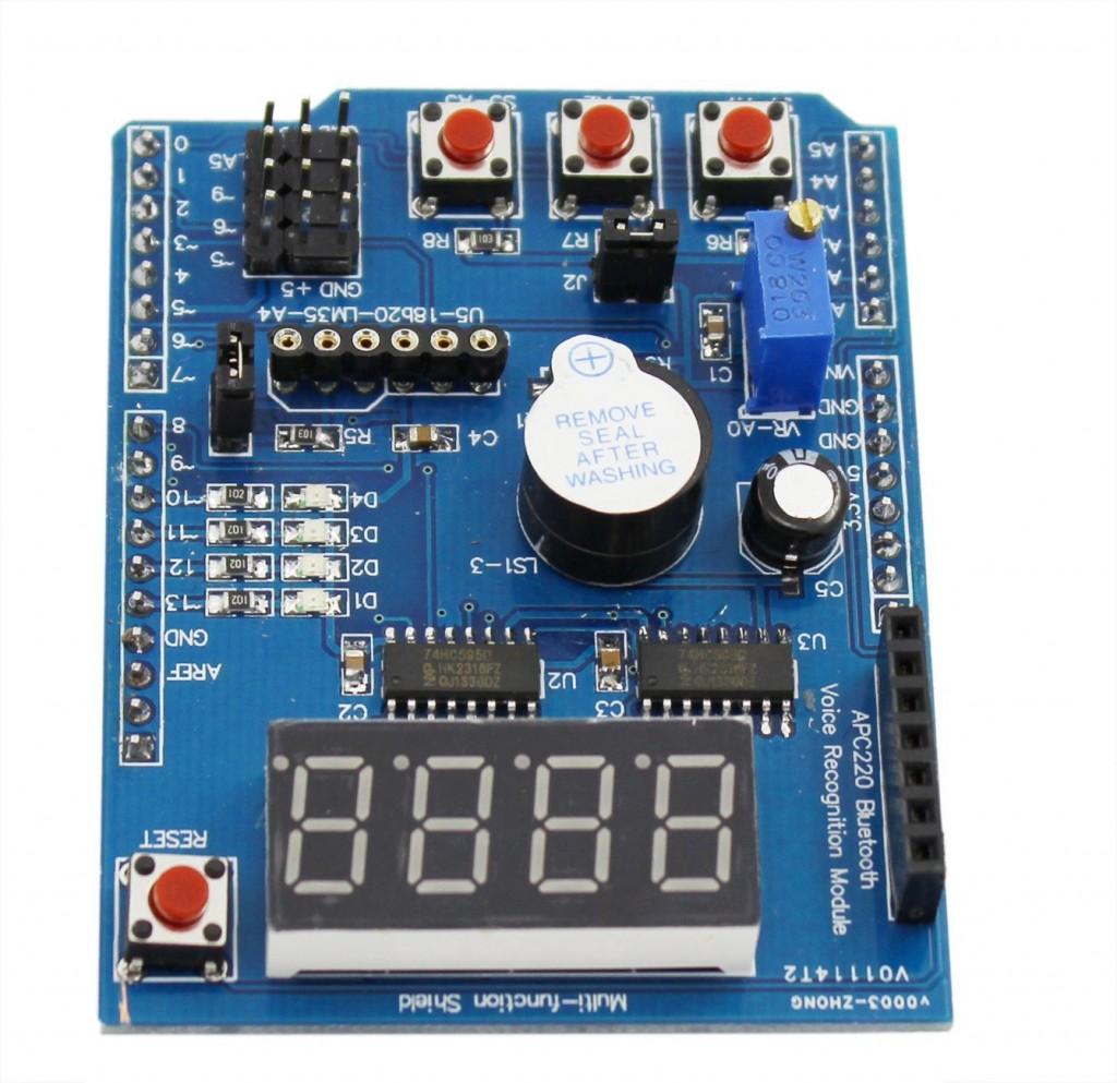
multi function shield
Features
4 digit 7-segment LED display module driven by two serial 74HC595’s
4 LED’s
10K potentiometer
3 x push buttons
Piezo buzzer
DS18B20 temperature sensor interface (not included)
Infrared receiver interface
Serial interface header for connection to serial modules
Code Examples
********************************************************************
Blinking LED
|
1
2
3
4
5
6
7
8
9
10
11
12
13
14
15
|
int led = 13;void setup(){// initialize the digital pin as an output.pinMode(led, OUTPUT);}void loop(){digitalWrite(led, HIGH);delay(1000);digitalWrite(led, LOW);delay(1000);} |
********************************************************************
All LEDS blinking
|
1
2
3
4
5
6
7
8
9
10
11
12
13
14
15
16
17
18
19
20
21
22
23
24
25
26
27
|
int led1 = 13;int led2 = 12;int led3 = 11;int led4 = 10;void setup(){// initialize the digital pin as an output.pinMode(led1, OUTPUT);pinMode(led2, OUTPUT);pinMode(led3, OUTPUT);pinMode(led4, OUTPUT);}void loop(){digitalWrite(led1, HIGH);digitalWrite(led2, HIGH);digitalWrite(led3, HIGH);digitalWrite(led4, HIGH);delay(1000);digitalWrite(led1, LOW);digitalWrite(led2, LOW);digitalWrite(led3, LOW);digitalWrite(led4, LOW);delay(1000);} |
********************************************************************
Switches example
|
1
2
3
4
5
6
7
8
9
10
11
12
13
14
15
16
17
18
19
20
21
22
23
24
25
26
27
28
29
30
31
32
33
|
const byte LED[] = {13,12,11,10};#define BUTTON1 A1#define BUTTON2 A2void setup(){// initialize the digital pin as an output./* Set each pin to outputs */pinMode(LED[0], OUTPUT);pinMode(LED[1], OUTPUT);pinMode(LED[2], OUTPUT);pinMode(LED[3], OUTPUT);}void loop(){if(!digitalRead(BUTTON1)){digitalWrite(LED[0], HIGH);digitalWrite(LED[1], HIGH);digitalWrite(LED[2], HIGH);digitalWrite(LED[3], HIGH);}if(!digitalRead(BUTTON2)){digitalWrite(LED[0], LOW);digitalWrite(LED[1], LOW);digitalWrite(LED[2], LOW);digitalWrite(LED[3], LOW);}} |
********************************************************************
Potentiometer 1
|
1
2
3
4
5
6
7
8
9
10
11
12
13
14
15
16
|
#define Pot1 0void setup(){Serial.begin(9600);}/* Main Program */void loop(){Serial.print(“Potentiometer reading: “);Serial.println(analogRead(Pot1));/* Wait 0.5 seconds before reading again */delay(500);} |
********************************************************************
Pot and led
|
1
2
3
4
5
6
7
8
9
10
11
12
13
14
15
16
17
18
19
20
21
22
23
24
25
26
27
28
29
30
31
32
33
34
35
36
37
38
39
40
41
|
const byte LED[] = {13,12,11,10};#define Pot1 0void setup(){Serial.begin(9600);// initialize the digital pin as an output./* Set each pin to outputs */pinMode(LED[0], OUTPUT);pinMode(LED[1], OUTPUT);pinMode(LED[2], OUTPUT);pinMode(LED[3], OUTPUT);}/* Main Program */void loop(){int PotValue;//Serial.print(“Potentiometer reading: “);PotValue = analogRead(Pot1);/* Wait 0.5 seconds before reading again */if(PotValue < 400){digitalWrite(LED[0], LOW);digitalWrite(LED[1], LOW);digitalWrite(LED[2], LOW);digitalWrite(LED[3], LOW);Serial.print(“Potentiometer: “);Serial.println(PotValue);}else{digitalWrite(LED[0], HIGH);digitalWrite(LED[1], HIGH);digitalWrite(LED[2], HIGH);digitalWrite(LED[3], HIGH);Serial.print(“Potentiometer: “);Serial.println(PotValue);}delay(500);} |
********************************************************************
segment display
|
1
2
3
4
5
6
7
8
9
10
11
12
13
14
15
16
17
18
19
20
21
22
23
24
25
26
27
28
29
30
31
32
33
34
35
36
37
|
/* Define shift register pins used for seven segment display */#define LATCH_DIO 4#define CLK_DIO 7#define DATA_DIO 8/* Segment byte maps for numbers 0 to 9 */const byte SEGMENT_MAP[] = {0xC0,0xF9,0xA4,0xB0,0x99,0x92,0x82,0xF8,0X80,0X90};/* Byte maps to select digit 1 to 4 */const byte SEGMENT_SELECT[] = {0xF1,0xF2,0xF4,0xF8};void setup (){/* Set DIO pins to outputs */pinMode(LATCH_DIO,OUTPUT);pinMode(CLK_DIO,OUTPUT);pinMode(DATA_DIO,OUTPUT);}/* Main program */void loop(){/* Update the display with the current counter value */WriteNumberToSegment(0 , 0);WriteNumberToSegment(1 , 1);WriteNumberToSegment(2 , 2);WriteNumberToSegment(3 , 3);}/* Write a decimal number between 0 and 9 to one of the 4 digits of the display */void WriteNumberToSegment(byte Segment, byte Value){digitalWrite(LATCH_DIO,LOW);shiftOut(DATA_DIO, CLK_DIO, MSBFIRST, SEGMENT_MAP[Value]);shiftOut(DATA_DIO, CLK_DIO, MSBFIRST, SEGMENT_SELECT[Segment] );digitalWrite(LATCH_DIO,HIGH);} |
********************************************************************
Read pot and display value on display
|
1
2
3
4
5
6
7
8
9
10
11
12
13
14
15
16
17
18
19
20
21
22
23
24
25
26
27
28
29
30
31
32
33
34
35
36
37
38
39
40
41
42
43
|
/* Define shift register pins used for seven segment display */#define LATCH_DIO 4#define CLK_DIO 7#define DATA_DIO 8#define Pot1 0/* Segment byte maps for numbers 0 to 9 */const byte SEGMENT_MAP[] = {0xC0,0xF9,0xA4,0xB0,0x99,0x92,0x82,0xF8,0X80,0X90};/* Byte maps to select digit 1 to 4 */const byte SEGMENT_SELECT[] = {0xF1,0xF2,0xF4,0xF8};void setup (){Serial.begin(9600);/* Set DIO pins to outputs */pinMode(LATCH_DIO,OUTPUT);pinMode(CLK_DIO,OUTPUT);pinMode(DATA_DIO,OUTPUT);}/* Main program */void loop(){int PotValue;PotValue = analogRead(Pot1);Serial.print("Potentiometer: ");Serial.println(PotValue);/* Update the display with the current counter value */WriteNumberToSegment(0 , PotValue / 1000);WriteNumberToSegment(1 , (PotValue / 100) % 10);WriteNumberToSegment(2 , (PotValue / 10) % 10);WriteNumberToSegment(3 , PotValue % 10);}/* Write a decimal number between 0 and 9 to one of the 4 digits of the display */void WriteNumberToSegment(byte Segment, byte Value){digitalWrite(LATCH_DIO,LOW);shiftOut(DATA_DIO, CLK_DIO, MSBFIRST, SEGMENT_MAP[Value]);shiftOut(DATA_DIO, CLK_DIO, MSBFIRST, SEGMENT_SELECT[Segment] );digitalWrite(LATCH_DIO,HIGH);} |
********************************************************************